
R&D · Product Development
Thermal and Structural Analysis of Automotive Headlamps
Our CAE unit combines conjugate CFD with finite element analysis to predict, explain, and fix overheating, resonance, and overstress in lamp assemblies before the first prototype is built.
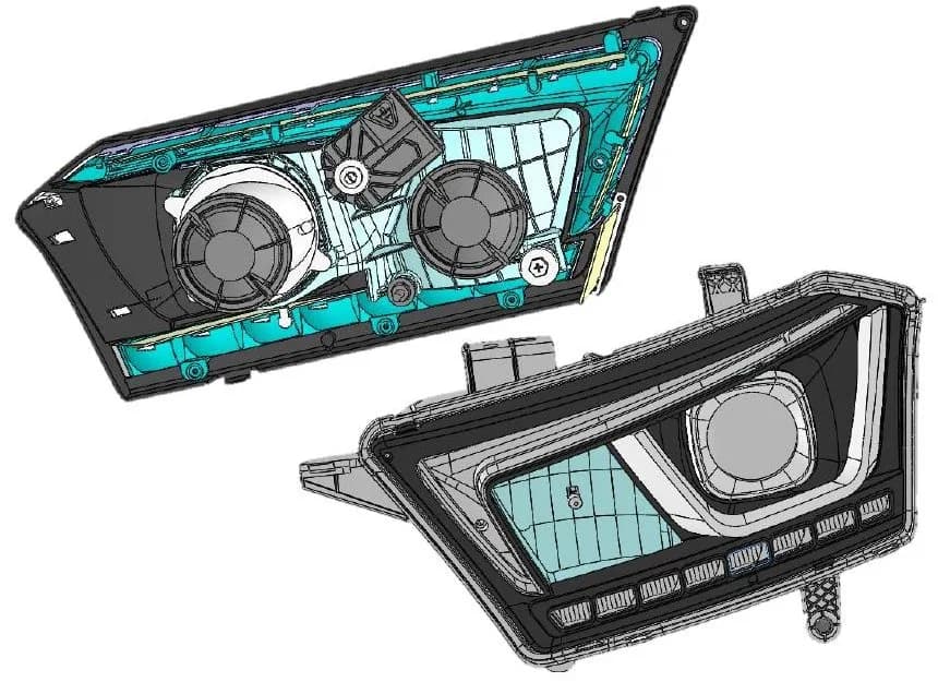
Three analyses, one model
- Thermal01
Conjugate CFD
Conduction, natural convection, radiation
- Modal02
Natural frequencies
Resonance under operational vibration
- Stress03
Finite element analysis
Stress distribution and durability
What We Analyse
Heat, Vibration, and Stress, Analysed Together
A headlamp brings heat sources, plastic components, and trapped air together in a compact, enclosed space, while also having to withstand road-induced vibration and mechanical loads. We perform thermal and structural analyses in parallel to evaluate all three factors in a single, integrated design review.
Thermal analysis
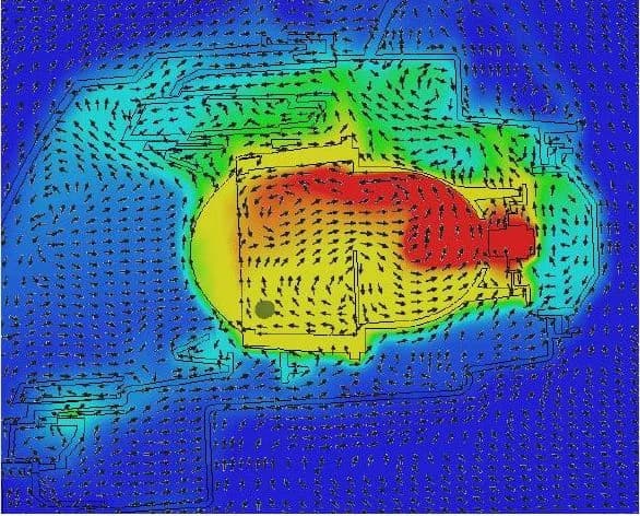
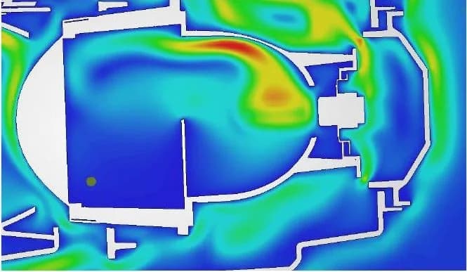
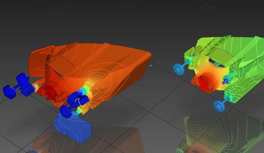
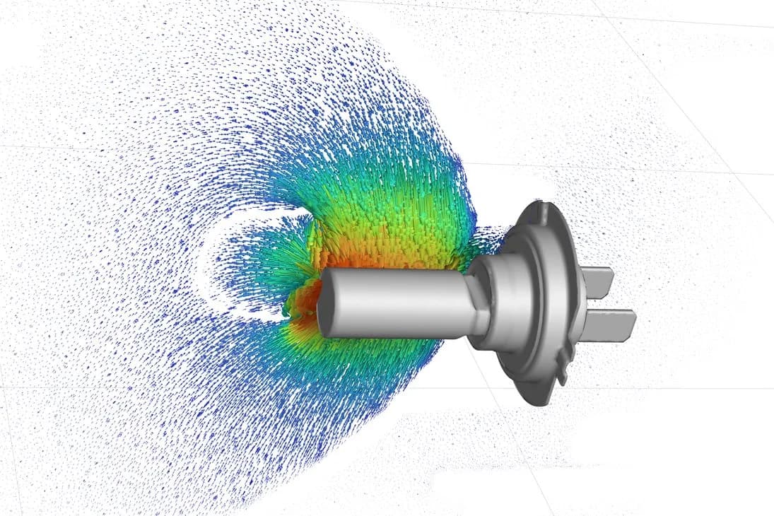
Heat is transferred by thermal radiation from hot surfaces, natural convection of heated air within the housing, and conduction through contact with adjacent hot components. Thermal analysis evaluates temperature distribution and identifies potential hot spots to prevent overheating and material damage.
Modal analysis
Identifying natural frequencies and mode shapes to assess the vibration behaviour of lamp assemblies and identify potential resonance risks under operational and road-induced vibration. This helps optimise structural stiffness and reduce excessive vibration and fatigue-related damage.
Stress and fatigue analysis
Evaluating stress distribution, stress concentrations, and structural deformation under mechanical and thermal loads to assess the integrity and durability of headlamp assemblies. This helps identify potential failure locations and improve reliability under demanding operating conditions.
01 / 03
Our Thermal Analysis Workflow
Our thermal analysis workflow evaluates the thermal behaviour of components and systems under specified operating conditions. It identifies temperature distributions, heat transfer mechanisms, and potential thermal issues, supporting design optimisation, better thermal performance, and reliable operation.
- Step 01
Geometry Preparation and Model Simplification
We review the CAD geometry and simplify the model while preserving the features that significantly influence heat transfer, including critical interfaces, contact surfaces, thin sections, and regions exposed to thermal loads.
- Step 02
Material Properties and Thermal Boundary Conditions
We define the relevant thermal properties, including thermal conductivity, specific heat capacity, and density, as required by the selected analysis. We also establish appropriate thermal boundary conditions, such as prescribed temperatures, heat fluxes, heat generation, convection, and radiation, to represent the intended operating environment.
- Step 03
Finite Element Modelling and Mesh Generation
We develop the finite element model and generate a suitable mesh to capture temperature gradients and heat transfer behaviour. Mesh refinement is applied in critical regions where steep thermal gradients or localised heat transfer effects are expected, and mesh quality is assessed to support reliable numerical results.
- Step 04
Thermal Analysis Setup
We configure the thermal analysis based on the physical problem and operating conditions. Depending on the application, we perform steady-state thermal analysis to determine temperature distributions under equilibrium conditions, or transient thermal analysis to evaluate temperature changes over time.
- Step 05
Solving and Thermal Results Evaluation
We solve the finite element model to determine the temperature field and relevant heat transfer parameters. The results are evaluated to identify hot spots, temperature gradients, heat flux paths, and regions with potentially inadequate thermal performance.
- Step 06
Thermal Performance Assessment
We compare the predicted temperatures and heat transfer results with material temperature limits, operating requirements, and applicable design criteria. Where relevant, we assess thermal expansion effects and temperature-induced stresses through coupled or sequential thermal-structural analysis.
- Step 07
Design Optimisation and Final Reporting
We identify opportunities to improve thermal performance through geometry changes, material selection, insulation, cooling strategies, or adjustments to boundary conditions. Finally, we document the analysis methodology, modelling assumptions, thermal results, critical regions, and engineering recommendations in a comprehensive technical report.
Results
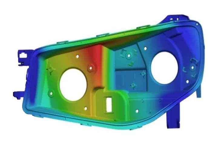
What the results show
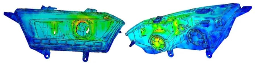
Numerical values and scales are omitted.
02 / 03
Our Modal Analysis Workflow
Our modal analysis workflow identifies the natural frequencies and mode shapes of a structure, helping us understand its dynamic behaviour and evaluate its susceptibility to vibration and resonance.
- Step 01
Geometry Preparation and Model Simplification
We review the CAD geometry, remove unnecessary details, and simplify the model while preserving the features that significantly influence the structure's dynamic response.
- Step 02
Material Properties and Boundary Conditions
We define the material properties, including density, Young's modulus, and Poisson's ratio, and establish appropriate boundary conditions to represent the actual support and connection conditions of the structure.
- Step 03
Finite Element Modelling and Mesh Generation
We generate a suitable finite element mesh and perform mesh quality checks so that the model accurately captures the structural deformation patterns and natural frequencies.
- Step 04
Modal Analysis Setup
We configure the modal analysis, select the required number of modes, and define the appropriate analysis method.
- Step 05
Solving and Mode Shape Evaluation
We solve the finite element model to determine its natural frequencies and corresponding mode shapes.
- Step 06
Results Interpretation and Design Assessment
We evaluate the natural frequencies and mode shapes against operating speeds, excitation frequencies, and relevant design requirements, and identify potential resonance risks and structural weaknesses.
- Step 07
Optimisation and Final Reporting
Where necessary, we recommend design changes, such as to stiffness, mass distribution, geometry, or support conditions, to improve the dynamic performance of the structure. Finally, we document the modelling assumptions, analysis results, and engineering recommendations in a comprehensive technical report.
Results
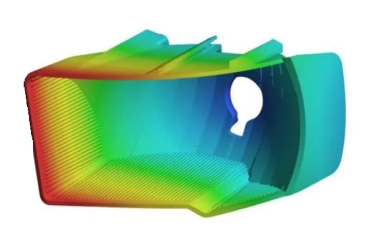
What the results show
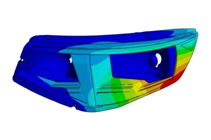
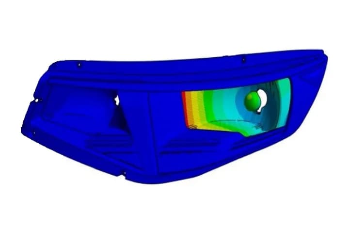
Numerical values and scales are omitted.
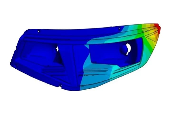
Mode 1
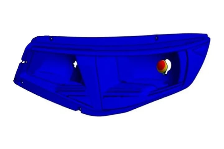
Mode 2
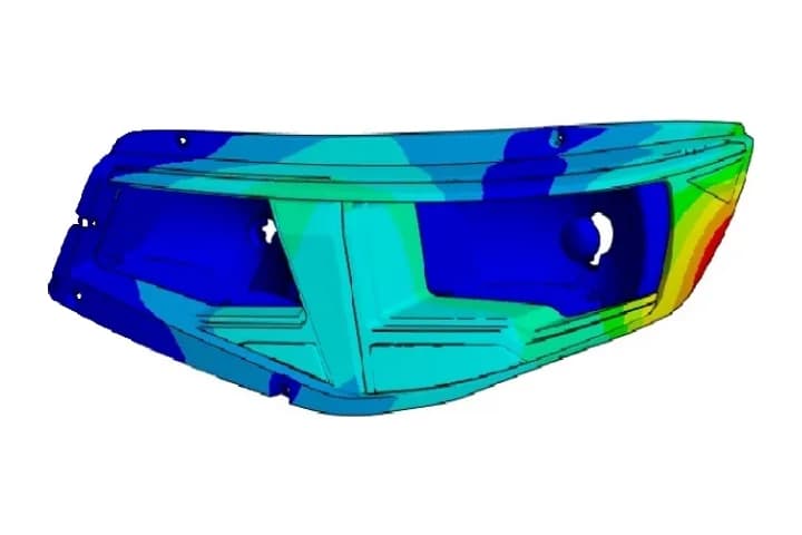
Mode 3
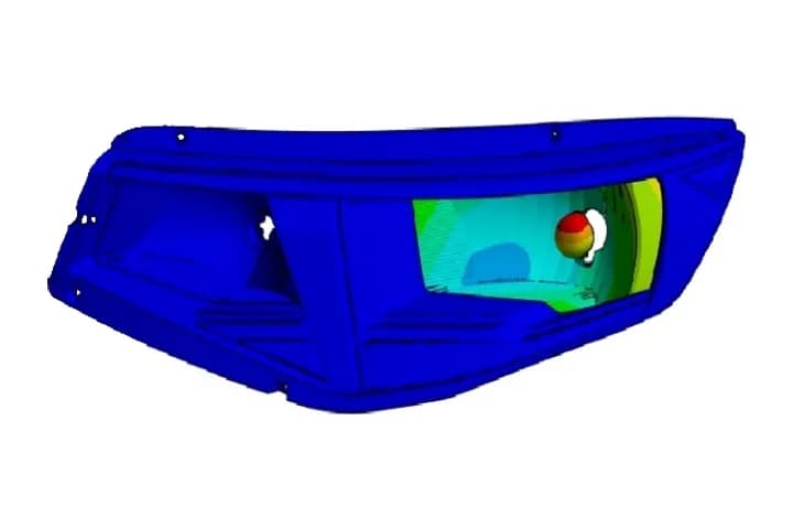
Mode 4
Mode 5
Mode 6
Modal analysis, total deformation for the first six vibration modes. Red areas move the most when the lamp vibrates at that natural frequency; blue areas barely move.
03 / 03
Our Stress and Fatigue Analysis Workflow
Our stress and fatigue analysis workflow evaluates structural integrity under applied loads and predicts fatigue performance under repeated or fluctuating loading. It identifies critical stress concentrations, assesses potential failure locations, and estimates component durability over its service life.
- Step 01
Geometry Preparation and Model Simplification
We review the CAD geometry and simplify the model while retaining critical features such as holes, fillets, notches, joints, and other geometric discontinuities that may influence stress concentrations and fatigue performance.
- Step 02
Material Properties and Loading Conditions
We define the relevant material properties, including elastic and, when required, plastic behaviour, yield strength, ultimate tensile strength, and fatigue data. We also establish the applied loads, moments, pressures, contact conditions, and boundary conditions based on the intended operating environment.
- Step 03
Finite Element Modelling and Mesh Refinement
We develop the finite element model and refine the mesh in critical regions where high stress gradients or stress concentrations are expected. Mesh quality and convergence are evaluated to improve the reliability of the calculated stresses.
- Step 04
Static Structural and Random Vibration Stress Analysis
We perform structural analysis to determine the stress and deformation fields under the specified loading conditions and base excitation. Depending on the application, we evaluate von Mises stress, principal stresses, shear stress, displacement, and other relevant mechanical response parameters.
- Step 05
Critical Stress Identification and Strength Assessment
We identify critical regions and compare the calculated stresses with appropriate material strength limits and design criteria. Where applicable, we evaluate yielding, local stress concentrations, and the structural factor of safety.
- Step 06
Fatigue Life and Damage Assessment
We evaluate fatigue performance under repeated or fluctuating loads using an appropriate fatigue assessment method. Depending on the loading characteristics and available material data, we apply the stress-life (S–N) method. Mean stress effects, notches, and cumulative damage may also be considered where relevant.
- Step 07
Design Optimisation and Final Reporting
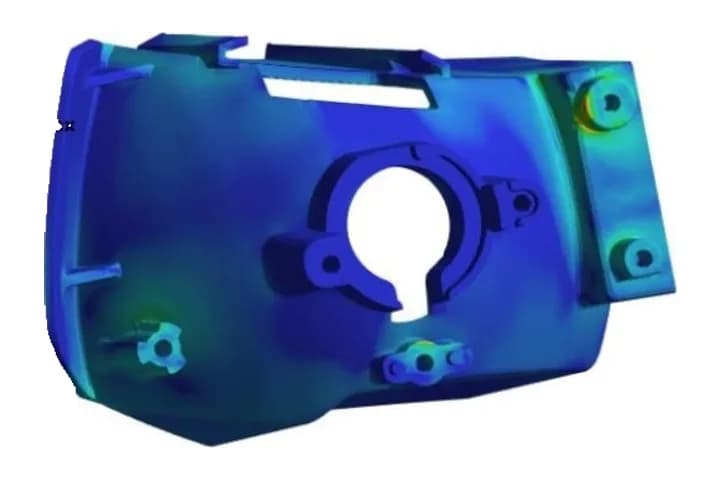
We identify opportunities to improve structural strength and fatigue resistance through geometry optimisation, stress concentration reduction, material selection, or changes in loading and support conditions. The final report summarises the analysis methodology, assumptions, stress distribution, critical locations, estimated fatigue life, and engineering recommendations.
Results
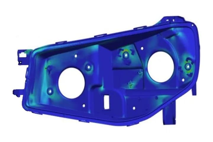
What the results show
Numerical values and scales are omitted.
Low-beam reflector
Housing
Business Inquiry
Validate a lamp design before tooling
Contact Modern Group to discuss thermal, modal, or stress and fatigue analysis for a lighting programme.