
R&D · Product Development
Development Process
Design and engineering from idea to production, built on APQP and the V-Cycle.
01 / 12
Design and Engineering Strategy
- Frameworks
- APQPV-CycleDFMEAPPAP
Our design and engineering strategy is built on the V-Cycle and APQP requirements, with a focus on requirements management, risk prevention and management, and engineering decisions based on data and evidence.
Customer requirements, standards, and legal requirements are identified early and turned into measurable technical specifications. Development covers design, engineering analysis, risk assessment, prototyping, and verification and validation testing, and at every stage the results are checked against the defined requirements.
Test results and engineering analysis drive continuous design improvement and risk control. The approved product, together with its requirements and critical characteristics, then moves in a controlled way into process development and mass production.
Strategic framework
- 01Requirements
- 02APQP
- 03Design
- 04DFMEA
- 05Verification
- 06Validation
- 07PPAP
- 08Mass production
- 09Continuous improvement
1.1
Product Development Approach
The product development cycle follows the APQP (Advanced Product Quality Planning) framework and is structured as a V-Cycle. This links and traces customer requirements, technical and legal requirements, design, analysis and risk management, verification, validation, and final product approval.
Each stage has defined inputs, activities, outputs, and evaluation criteria, and its results are the basis for entering the next stage. At each control point, design results, engineering analysis, risk assessments, and tests are reviewed, and the decision to proceed is made on the evidence.
Together, APQP and the V-Cycle manage development from requirements definition to final approval and controlled transfer to production in a way that is structured, traceable, and focused on risk prevention and quality assurance.
1.2
Verification and Validation
For each requirement and important product characteristic, a specific, measurable verification method is defined to check that design outputs meet the set requirements and specifications. This can include engineering reviews, analysis, dimensional inspection, functional tests, and other methods suited to the requirement.
Once verification is complete and the design is confirmed to conform, validation checks how the product performs in real or simulated use, in line with customer needs. This stage assesses performance, reliability, and fitness for the intended application and customer requirements.
Verification and validation results are documented and serve as objective evidence of conformity and as the basis for final design approval and release to mass production.
Key Principles
What every project is built on
Engineering vision
A product development system that defines requirements correctly, anticipates risks, validates the design, and moves the product into mass production with confidence.
Customer Focus
Customer requirements, legal requirements, and performance expectations are the basis for defining specifications and making design decisions.
Prevention-Based Design
Design risks are identified early and reduced with DFMEA and preventive action.
Design for Manufacturing
Manufacturability, assembly, quality control, and process stability are considered from the start of design, so the product is developed with minimal complexity and production risk.
Data-Driven Engineering
Design decisions are made and confirmed on the basis of simulation results, engineering analysis, tests, and real product data.
Controlled Transfer to Production
The product moves from design to production in a controlled way, based on engineering outputs and APQP requirements. Production and quality requirements are kept intact, and technical knowledge and requirements are handed over to production systematically.
Product Lifecycle Management
Engineering changes, production feedback, and product performance over its lifecycle feed continuous improvement of the design and the development process.
Design and Engineering Processes
From requirements to series production
Automotive lighting products are designed and developed on the basis of customer requirements, automotive industry standards, and legal requirements, following APQP and a V-Cycle structure.
Product requirements are followed step by step from definition and initial analysis through design, engineering, risk assessment, prototyping, and testing. The V-Cycle links design activities to their validation stages, so product performance can be checked and confirmed at every stage of development.
APQP, with its focus on quality planning, risk management, change control, and production readiness, steers development through to a successful transfer to series production. The result is products with consistent quality and performance that meet customer requirements and the relevant regulations and are ready for industrial production.
02 / 12
Requirements Analysis and Development Planning
- Initial documents
- BOMOPCF-Release 3D files
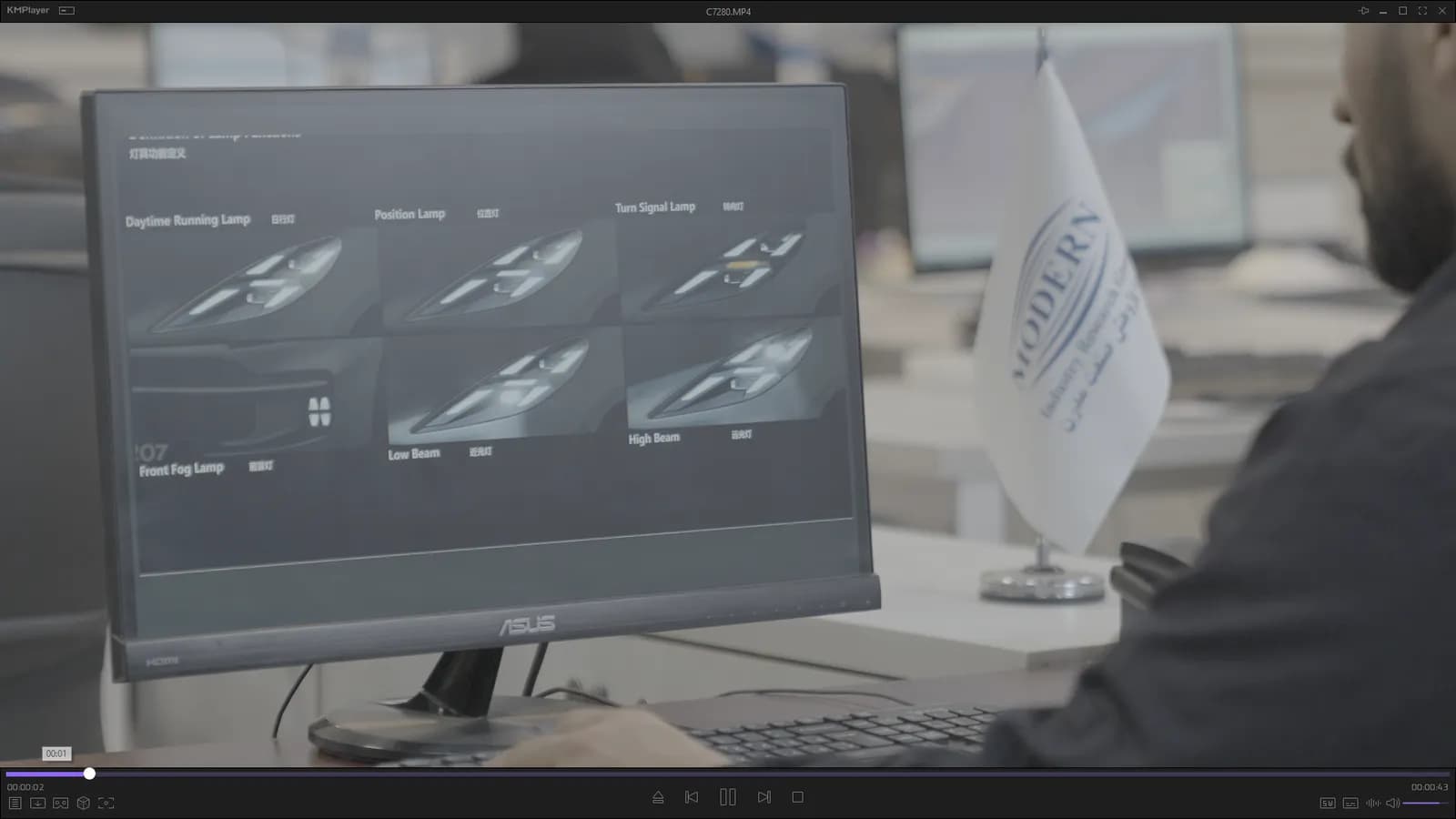
At the start of a project, customer requirements, legal requirements, technical standards, and the product's functional requirements are identified, reviewed, and analysed. A technical and manufacturing feasibility check confirms the requirements can be met and identifies design and production constraints.
Taking packaging constraints and mounting conditions into account, the initial engineering documents, including the BOM, OPC, and F-Release 3D files, are prepared and form the basis for the next design and development stages.
03 / 12
Technical and Manufacturing Feasibility
- Assessed
- Functional and technical requirementsOptical and lighting requirementsMaterials, parts, and technologiesDesign, manufacture, and assemblyProduction equipment and capacityTesting and validationSupply and material availabilityQuality, timing, and cost
- Main outputs
- Product requirements and specificationsTechnical requirementsFeasibility studiesProduct development planInitial BOM and OPCF-Release 3D files
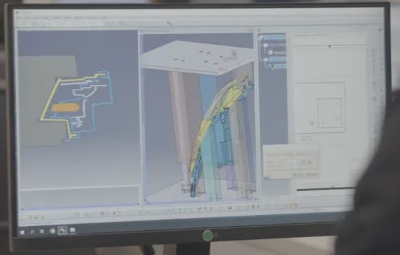
Before design and development begin, customer requirements, technical specifications, legal requirements, and the relevant standards are reviewed and the ability to meet them is assessed.
Technical, engineering, manufacturing, and supply capability are reviewed alongside product and process constraints, so potential risks are found early.
The results are the basis for deciding whether to accept the project, defining engineering requirements, planning development, and identifying early risks. The aim is to make sure project requirements can be met before design and development start, and to stop risk being carried into later stages.
Feasibility is assessed jointly by engineering, quality, production, and supply, and its results are one of the inputs to product quality planning.
04 / 12
Product Design and Development
- Main outputs
- 3D modelsEngineering drawingsMaterial specificationsProduct specificationsCritical characteristicsA-Release 3D and 2D files
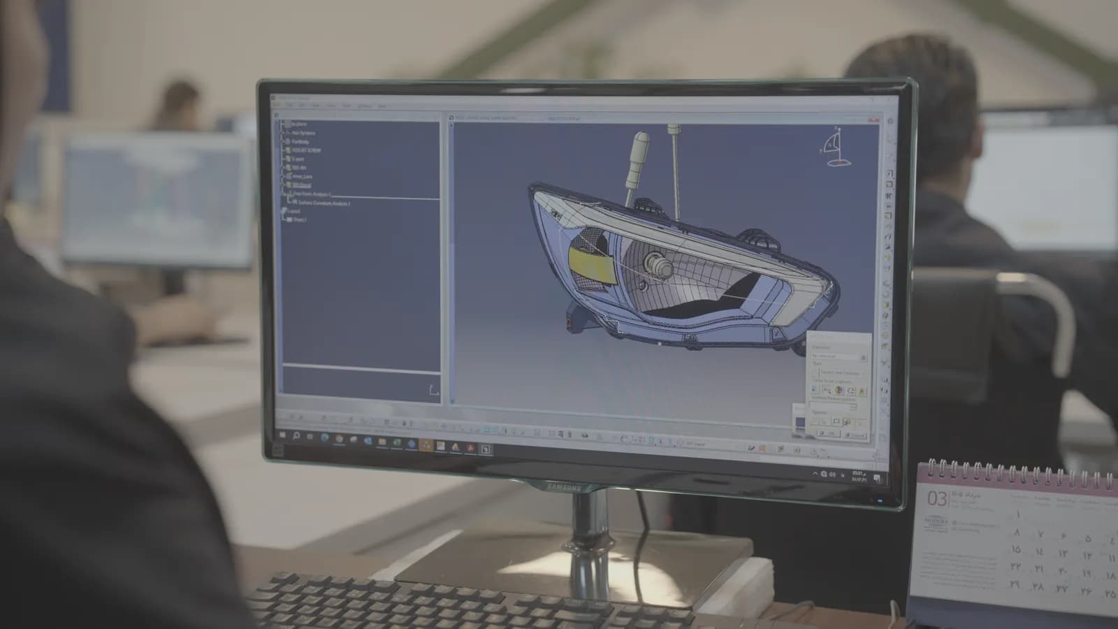
Lamps are designed and developed with the technical and functional requirements, manufacturability and assembly, durability, and vehicle operating conditions in mind. Mechanical, optical, and functional parts are developed together using engineering tools, 3D modelling, and detailed design.
Engineering drawings and specifications, material selection and specification, critical product characteristics, and manufacturing and assembly requirements are also defined, so the product is ready for prototyping, testing, and validation.
Updated BOM and OPC documents and the A-Release 3D and 2D files are issued in this phase.
05 / 12
CAE and Simulation-Driven Engineering
- Simulation
- OpticalVibrationThermalDFMEA
CAE (computer-aided engineering) lets us predict how a lamp will behave and perform before a physical prototype is built. Optical, thermal, and vibration simulations find critical points in the design, assess the strength and durability of parts, and check the lamp's operating conditions, which helps optimise the design and reduce development risk.
Used alongside physical thermal and vibration tests, CAE results give a more precise validation of the design and more confidence in the performance and durability of each lamp.
5.1
Optical and Lighting Simulation
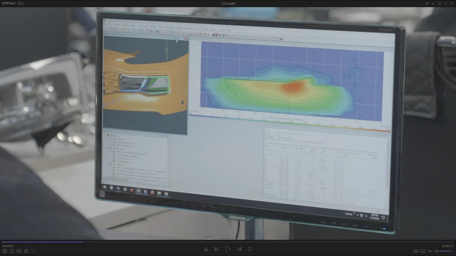
The optical system is designed and optimised with specialist optical simulation and analysis software, including LucidShape, Ansys Speos, and LightTools. Light distribution, intensity, uniformity, beam coverage, and photometric performance are assessed for each lamp type.
Simulation results are used before the first prototype to refine the optical geometry, light sources, reflectors, lenses, and other parts that affect optical performance. This cuts the number of prototype and test rounds and reaches the functional and legal requirements faster.
Optical performance is assessed to the regulations that apply to the lamp type and target market, including UN R149, R148, R48, R87, R19, R6, R7, R23, R38, and R91.
- Software
- LucidShapeAnsys SpeosLightTools
- Outputs
- Simulation model and resultsPhotometric specificationLight distribution mapHomologation requirements
- Regulations
- UN R149R148R48R87R19R6R7R23R38R91
5.2
Vibration Simulation
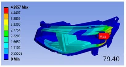
CAE vibration simulation before the first prototype predicts structural behaviour, finds critical points, checks stress and deformation, and lets the design be corrected before parts are made and physically tested. This shortens development and lowers its cost while giving more confidence in the design.
Once the design is approved, a vibration test assesses how the lamp and its internal parts withstand the vibration and mechanical loads of real vehicle use. It checks the strength of joints and parts, deformation, cracking or breakage, and the lamp's optical, electrical, and mechanical function. Mechanical load conditions are set by mounting location to ISO 16750-3:2023 (Mechanical Loads).
The UN/ECE requirements for the lamp type and application also apply: UN R48 for installation of lighting and light-signalling devices, UN R148 for light-signalling devices, and UN R149 for road illumination devices.
- Standards
- ISO 16750-3:2023UN R48UN R148UN R149
5.3
Thermal Simulation
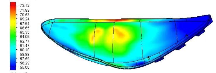
To make sure the lamp performs and lasts in real conditions, CAE thermal simulation is carried out before the first prototype. Analysing temperature distribution and heat transfer and finding hot spots lets us optimise the design and prevent thermal problems early. Once the design is approved, thermal performance and durability are also assessed in thermal and climatic tests.
These tests check how parts, light sources, and electronics behave, the stability of optical performance, sealing, and the assembly's resistance to temperature changes and thermal stress. The process covers every lamp type, including headlamps, rear lamps, fog lamps, indicators, DRL, and side lamps, according to product requirements and mounting location.
Combining CAE simulation with physical tests lets us optimise the design before production, reduce the risk of failure, and make sure the lamp performs reliably and lasts in different operating and environmental conditions. Thermal tests and assessments follow the project requirements and the relevant standards and regulations, including ISO 16750-4:2023, UN R48, UN R148, and UN R149.
- Standards
- ISO 16750-4:2023UN R48UN R148UN R149
5.4
Design Risk Analysis (DFMEA)
Potential design risks are identified and assessed systematically. DFMEA is used during design and development to prevent possible failures, identify critical characteristics, and define risk-reduction actions. Its results are a key input to design validation and production process development.
06 / 12
Product Development on the V-Cycle
Product development is organised as a V-Cycle, which links and traces customer needs, product requirements, design, development, verification, and validation across the whole product lifecycle.
Product requirements and characteristics are identified and documented at the start of the project, with a suitable review and approval method defined for each. The results of analysis, tests, and assessments are then matched against the original requirements, so conformity with the technical specification is shown in a traceable, documented way.
This reduces development risk, finds discrepancies early, and confirms the product meets its requirements before it enters production.
Overall development path
- 01Requirement
- 02Design
- 03Development
- 04Verification
- 05Validation
- Customer and Vehicle RequirementsProduction Validation and SOP
- Lamp System DesignSystem Testing
- Sub-System ArchitectureIntegration Testing
- Detailed Engineering DesignComponent and Sub-System Verification
- Prototype Build and Product Realisation
07 / 12
Prototyping and Design Verification
- Tests
- FunctionalDimensionalMaterialAssemblySpecialist
- Release
- T-Release 3D and 2D files
Engineering samples and prototypes are built to the development plan and evaluated for performance, manufacturability, and conformity with technical requirements and design specifications. The type and scope of testing depend on the product, the maturity of the sample, the results of engineering analysis, and customer requirements, and can include functional, dimensional, material, assembly, and other specialist tests.
Test and assessment results are recorded as design verification evidence and are the basis for deciding whether the design conforms and development can continue. If non-conformities or improvement opportunities are found, the design is corrected and the samples are evaluated again.
Once testing confirms the design meets technical and customer requirements, the design is finalised and the 3D and 2D files are released through T-Release for the next development steps and for tool and mould making. The final product specifications then become a main input to mould design and manufacture, production process development, and quality control planning.
08 / 12
Tooling
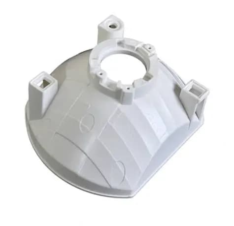
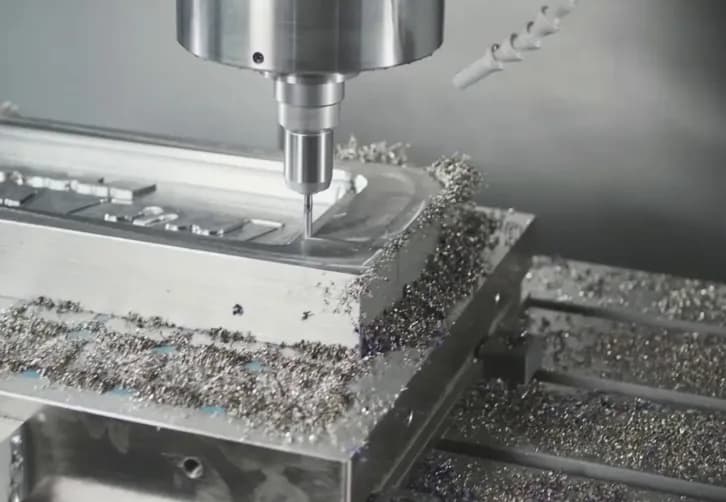
Once the design is approved, the finalised 3D models, engineering drawings, and technical specifications are the inputs to tooling and mould making. Mould design, manufacture, assembly, and any corrections take into account the design requirements, manufacturability, and production process requirements.
Initial parts from the mould are checked for dimensions, function, appearance, and quality, and the mould and process are corrected where needed. These results are the basis for approving the mould and the product's readiness for the next development and production stages.
The product made from the final mould is then tested under defined conditions suited to its end use, in real or simulated tests, to confirm it meets the technical, functional, legal, and customer requirements. Final approval of the mould, the product, and the test results is a key input to production process approval and the PPAP.
09 / 12
Validation and Transfer to Production
- Main outputs
- Process flowPFMEAControl planWork instructionsFinal engineering documents
- Release
- V-Release
Once testing is complete and the product is confirmed to meet technical, functional, and customer requirements, the design moves to final approval and transfer to production. Manufacturability, repeatability, and process stability are confirmed in close cooperation between product engineering, process engineering, and production.
Design outputs, including technical specifications, drawings, test results, and the DFMEA, become inputs to production process development and process risk assessment. Special product requirements, critical characteristics, and quality requirements identified during design are built into the production process and control plans.
The 3D and 2D files are revised and finalised, and with the V-Release all related technical documents are updated for the product's controlled entry into production.
10 / 12
PPAP: Product and Process Approval
In the PPAP (Production Part Approval Process) stage, the documents and objective evidence needed to approve the product and production process against technical, quality, and customer requirements are prepared and submitted. They are collected, reviewed, and controlled to the required PPAP level and are the basis for final product and process approval.
Design and development outputs, test and validation results, technical specifications, the DFMEA, and production process documents are brought together to show stable production capability and product conformity with customer requirements.
As a key milestone in APQP, PPAP links product design, process development, and the quality system, and prepares the ground for approving the product and process before production starts or expands.
11 / 12
Engineering Change Management
Any change to design, materials, parts, or the production process goes through engineering change control and is documented. Its effects on performance, quality, legal requirements, manufacturability, and other product characteristics are assessed, and the change is implemented only after the required approvals.
11.1
Engineering Documentation and Traceability
Design and development information and documents are controlled and kept up to date throughout the product lifecycle. Links between requirements, product specifications, design, DFMEA, test results, engineering changes, and PPAP documents make the development process traceable.
12 / 12
AI in Lamp Design and Development
- Where AI applies
- Concept and light-graphic designOptical design and optimisationTest analysis and validationDesign for mass production (DFM)Quality control and defect detectionPerformance and durability predictionGenerative design of lamp form
Artificial intelligence (AI) in lamp design and development allows faster analysis, a wider range of design options, and a more efficient development process. AI can work alongside design and engineering teams from early ideation and light-graphic design through to analysing and optimising lamp performance.
In design, AI can generate and evaluate lighting concepts, develop signature lighting, refine lamp form and graphics, and create lighting scenarios. In engineering, it can analyse design and test data, find patterns, optimise optical parameters, and help shorten development, making the engineering process faster and more precise.
Combining engineering and design experience with AI moves the development of next-generation lamps towards products that are smarter, more precise, and suited to the future needs of the automotive industry.
Engineering Approach
The methods behind the process
APQP
Structured planning and management of product quality.
V-Cycle
A systematic link between requirements, design, verification, and validation.
DFMEA
Identifying and reducing design risks.
Verification
Confirming the design conforms to its defined specifications.
Validation
Confirming product performance in real use.
PPAP
Evidence that the product and process meet customer requirements.
Final Goal
Develop products that meet their requirements, can be manufactured, are traceable, and are ready for mass production, with a focus on quality and consistent performance.
Business Inquiry
Develop a lighting product with us
Contact Modern Group to discuss a new lamp programme, from requirements and feasibility through to PPAP.